Elektrik - Best Electronic Projects Reviews
  • Home
  • Privacy Policy
  • About
  • Related

Sunday, 5 July 2015

Simple audio amplifier using LM386.

 dvbot     July 05, 2015     amplifier, breadboard, cheap, cheap amplifier, integrated circuit, LM386, low component, simple amplifier     No comments   

The LM386 is an audio amplifier designed for use in low voltage consumer applications. The gain is internally set to 20 to keep external part 
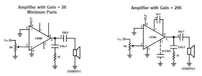
count low, but the addition of an external resistor and capacitor between pins 1 and 8 will increase the gain to any value from 20 to 200.

Parts will be assembled and connected according to the following schematic:

This project uses an integrated circuit with capacity of 10 transistors to amplify much better with much less power drain on the batteries than our simple amplifier.


Following parts are required:
  • A LM386 integrated circuit amplifier chip
    This is the main working part of the amplifier.
  • A small speaker
  • Some jumper wires 
  • 9 volt DC adapter of 2 Amps or more or  9 volt battery clip and  9 volt battery  

The Three Penny Radio normally has a piezoelectric earphone attached at points J-20 and E-22. We replace the earphone with our amplifier.
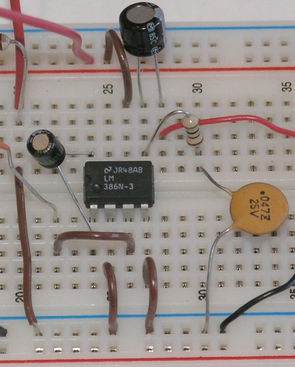
Below is a closeup of the amplifier section:
 

 Here you can see that we have connected the Three Penny Radio output at J-20 to the ground rail below the blue line. This rail has all of its holes connected together. We connect the black (negative) wire from the battery to the ground rail. We connect the red (positive) wire from the battery to the power rail, just above the red line at the top of the photo. Having the power and ground connected to these rails makes it easier to connect the other parts, and makes it easier to see where all the connections are.

You can connect your audio source instead of radio.

The other output from the Three Penny Radio us plugged into E-22.
Using the labeled grid as before, the parts are connected this way:
  • LM386 amplifier chip at E-24, E-25, E-26, E-27 and F-24, F-25, F-26, and F-27.
  • Jumper wire: F-20 to ground rail.
  • Jumper wire: C-22 to C-26.
  • Jumper wire: A-25 to ground rail.
  • Jumper wire: A-27 to ground rail.
  • Jumper wire: J-26 to power rail.
  • Speaker: red wire to H-27 and black wire to ground rail.
  • Negative 9 volt battery wire (black): ground rail.
  • Positive 9 volt battery wire (red): power rail.
When all the wires are connected properly, you should be able to hear radio stations coming from the speaker. They will not be particularly loud, but we can increase the volume 10-fold with a simple adjustment.


We put a 10 microfarad capacitor connecting pins 1 and 8 of the integrated circuit (put the negative capacitor lead into hole D-24 and the positive capacitor lead into hole G-24).

This bypasses a resistor inside the integrated circuit, boosting the gain from 20 to 200.

One problem with the circuit so far is that the speaker will get warm and the battery will not last long. This is because a certain amount of DC current is going through the speaker. Direct current (DC) does not make sounds, and so this current is a complete waste of battery power, and simply warms up the speaker coil.


We fix this problem by putting a 220 microfarad capacitor between the integrated circuit output pin (pin 5, in hole F-27) and the red speaker wire. The positive capacitor lead is put into hole J-27, and the negative capacitor lead is put into hole J-29. The red speaker wire is moved to hole G-29.

To prevent the capacitor from changing the sound, we add two more components to create a "filter" that lets only audio frequencies get to the speaker.


Here we have moved the negative lead of the 220 microfarad capacitor to hole J-28, and moved the red wire of the speaker to H-28. We put a 10 ohm resistor into holes G-27 and G-30. A 0.047 microfarad capacitor goes into hole F-30 and the ground rail.

Our amplifier is working pretty well now. But our little speaker has a high tinny voice, because of its size. It would be nice if it had a little more power on the lower frequencies, what we call "bass response".

We can arrange to amplify the lower frequencies more than the high ones. We make another filter from a 0.033 microfarad capacitor and a 10,000 ohm resistor, and connect that between the output pin and pin 1 of the integrated circuit. This will feed some of the low frequencies back into the amplifier to be amplified again.

We put the 10,000 ohm resistor in holes C-24 and F-29. We put the 0.033 microfarad capacitor in holes I-27 and I-29.


 The amplifier is now ready with much better sound.


  • Share This:  
  •  Facebook
  •  Twitter
  •  Google+
  •  Stumble
  •  Digg
Email ThisBlogThis!Share to XShare to Facebook
Newer Post Older Post Home

0 comments:

Post a Comment

Powered by Blogger.

Popular Posts

  • Simple +-400Watt Amplifier using TDA7294 or TDA7293 + Power Transistors 2SC5200 and 2SA1943
    This additional part can be added to the traditional chip amp made using TDA7294 or TDA7293 to gain extra power in output. The traditional...
  • Audio Amplifier - 2N3055 MJ2955
    Here is A amplifier with 2n3055 transistors on its output for those of you that are looking at doing a bang for buck amplifier with...
  • Stun Gun Circuit Diagram using 555 timer IC
    CAUTION: Before going to explain about this circuit, we are going to strictly suggest that DO NOT TRY TO IMPLEMENT IT PRACTICALLY AS IT P...
  • Simple 150 Watt amplifier circuit using transistors
    This is the cheapest 150 Watt amplifier circuit you can make,I think.Based on two Darlington power transistors TIP 142 and TIP 147 ,this ...
  • Make a solar cell in your kitchen
    A solar cell is a device for converting energy from the sun into electricity. The high-efficiency solar cells you can buy at Radio Shack a...

Pages

  • Home
  • Related
  • Privacy Policy
  • About

Blog Archive

  • ►  2017 (1)
    • ►  June (1)
  • ►  2016 (1)
    • ►  August (1)
  • ▼  2015 (23)
    • ►  December (1)
    • ►  November (2)
    • ►  October (2)
    • ►  September (2)
    • ►  August (4)
    • ▼  July (10)
      • Audio Clipping Peak Indicator using IC TL062
      • How to make a 2 Watt audio amplifier from discrete...
      • How to make your own simple 5pf Capacitor
      • Simple 150 Watt amplifier circuit using transistors
      • A Simple Day Light Sensor Circuit using cheap comp...
      • Cheapest High power LED driver circuit schematic
      • Simple and Cheap 100W Inverter Circuit
      • Lead Acid Battery Charger Circuit
      • Bipolar LED Driver Circuit
      • Simple audio amplifier using LM386.
    • ►  June (2)
  • ►  2013 (1)
    • ►  July (1)
  • ►  2011 (3)
    • ►  August (3)

Dear Visitor

Please leave a comment or contact if you liked the post.

Message me if you have any issues regarding anything on this blog. I'd be happy to help you out with it.

If you need a custom made circuit you can surely let me know through comments or Contact Form, I'll reply as soon as I see it.

Thank you.

Contact Form

Name

Email *

Message *

Labels

diy simple LED amplifier cheap simple amplifier 150W 2N3055 battery battery charger cheap amplifier circuit easy inverter circuit project semiconductor silicone transistor 100W inverter 10k free energy 10k to 25k volt capacitor 12 volt battery led driver for 5 watt and 3 watt 12 volt dc battery charger using lm317 with output display 150 watt 150 watt amplifier 2N3906 3 watt amplifier 5 Volt DC Regulator to charge mobile phones from 12 or more DC voltage 5 volt charger 500w inverter circuit 500watt inverter 5pf A564 BC548 BC558 BD139 BD140 Bipolar LED C1162 Corroded Momentary switches D438 HV capacitors IC LDR LED circuit LED driver LED driver circuit LM386 Lead Acid battery MJ2955 Making your own 10k capacitor Momentary switches Remote control switch on or off for home appliances TIP142 TIP147 UM66 amplifier level indicator amplifier using TDA2003 android charger arduina is easy arduino arduino mega and uno arduino programming arduino web server atmega328 audio amplifier bd679 stun gun breadboard capacitor capacitors caps car amplifier car tail light led driver cell cell phone charger charger circuit cheap circuit corrected circuit country style day light sensor diy capacitor diy hack diy simple boat electrics electric ethernet shield free energy free power source girlfriend how do solar panels work how to fix horn button how to fix switches on boat hv caps ic TL062 integrated circuit introduction inverter using 2n3055 iphone charger kitchen led driver for vehicle like motorbike and car led driver using lm338 led track lighting lm317 ic low component make your own make your own capacitor mice problems modern lighting moon motor mouse mouse click mouse click issues mouse issues mouse left click issues mouse not working mouse right click issues peak level indicator phone charger photovoltaic powerful amplifier using tda7293 and tda7294 using extra transistors 2sc5200 and 2sa1943 relationship renewable energy repair samsung charger simple auto amplifier simple boat switch fix simple circuit simple inverter simple peak level simple web server solar solar energy solar panels stun gun using 555 timer ic timer ic 555 track track lighting transistor and chip amp hybrid using IC CD4017 what is arduino why arduino working simple working with relations

Report Abuse

About Me

dvbot
View my complete profile

Elektrik - Best Electronic Projects Reviews

Loading...

Loading...

Translate

Recent

Subscribe To

Posts
Atom
Posts
Comments
Atom
Comments

Copyright © Elektrik - Best Electronic Projects Reviews
Distributed By My Blogger Themes | Blogger Theme By NewBloggerThemes