Elektrik - Best Electronic Projects Reviews
  • Home
  • Privacy Policy
  • About
  • Related

Tuesday, 7 July 2015

Simple and Cheap 100W Inverter Circuit

 dvbot     July 07, 2015     100W inverter, inverter circuit, simple circuit, simple inverter     2 comments   

Inverter is a small circuit which will convert the direct current (DC) to alternating current (AC). The power of a battery is converted in to’ main voltages’ or AC power. This power can be used for electronic appliances like television, mobile phones, computer etc. the main function of the inverter is to convert DC to AC and step-up transformer is used to create main voltages from resulting AC.


Simple and Cheap 100W Inverter Circuit using mosfets CD4047 IRF540

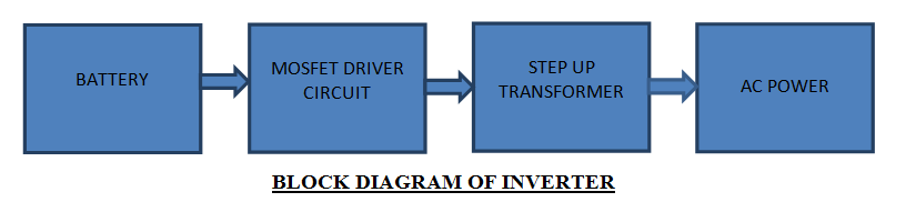
In the block diagram battery supply is given to the MOSFET driver where it will convert DC to AC and the resulting AC is given to the step up transformer from the step up transformer we will the get the original voltage.


Main Components:

CD4047: CD4047 is a multi vibrator with very low power consumption designed by TEXAS INSTRUMENTS.it can operate in monostable multivibrator and also astable multivibrator.in the astable multivibrator mode it can operate in free running or gatable modes and also provides good astable frequency stability. It can generate 50% duty cycle which will create a pulse, which can be applied for inverter circuit. This is mainly used in frequency discriminators, timing circuits frequency divisions etc.

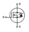
IRF540: IRF540 is a N-channel enhanced mode silicon gate field effect transistor (MOSFET).they are mainly used in switching regulators, switching converters relay drivers etc. the reason for using them in the INVERTER circuit is the because it is a high switching transistor , can work in very low gate drive power and have high input impedance.

IRF540 Symbol:

Simple and Cheap 100W Inverter Circuit using mosfets CD4047 IRF540 

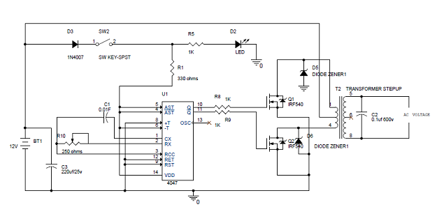
Simple 100W Inverter Circuit Diagram:

Simple and Cheap 100W Inverter Circuit using mosfets CD4047 IRF540

 Explanation:

  • In the circuit diagram we can observe that 12V battery is connecter to the diode LED and also connected to the pin8 of the IC 4047 which is VCC or power supply pin and also to pin 4 and 5 which are astable and  complement astable of  the IC. Diode in the circuit will help not give any reverse current, LED will work as a indicator to the battery is working or not.
  •  IC CD4047 will work in the astable multivibrator mode. To work it in astable multivibrator mode we need an external capacitor which should be connected between the pin1 and pin3. Pin2 is connected by the resistor and a variable resistor to change the change the output frequency of the IC. Remaining pins are grounded .The pins 10 and 11 are connected to the gate of the mosfets IRF540. The pin 10 and 11 are Q and ~Q from these pins the output frequencies is generated with 50% duty cycle.
  • The output frequency is connected to the mosfets through resistor which will help to prevent to the loading of the mosfets. The main AC current is generated by the two mosfets which will act as a two electronic switches. The battery current is made to flow upper half or positive half of the primary coil of transformer through Q1 this is done when the pin 10 becomes high and lower half or negative half is done by opposite current flow through the primary coil of transformer, this is done when pin 11 is high. By switching the two mosfets current is generated.
  • This AC is given to the step up transformer of the secondary coil from this coil only we will get the increased AC voltage , this AC voltage is so high; from step up transformer we will get the max voltage. Zenor diode will help avoid the reverse current. 

NOTE: The generated AC is not equal to the normal AC mains or house hold current. You cannot use this voltage for pure electric appliances like heater, electric cooker etc. Because of the fast switching of mosfets heat is dissipated which will effect the efficiency, use heat sink to remove this problem. The transformer can be bought through transformer manufacturer in your city or town.

  • Share This:  
  •  Facebook
  •  Twitter
  •  Google+
  •  Stumble
  •  Digg
Email ThisBlogThis!Share to XShare to Facebook
Newer Post Older Post Home

2 comments:

  1. Siddhartha28 January 2016 at 20:49

    Good job ! 7 months and no comments !! Did you try this circuit out ?

    ReplyDelete
    Replies
    1. dvbot29 January 2016 at 06:09

      I did try this one. Meanwhile, you too have an awesome blog. Keep it up dude.

      Delete
      Replies
        Reply
    2. Reply
Add comment
Load more...

Powered by Blogger.

Popular Posts

  • Simple +-400Watt Amplifier using TDA7294 or TDA7293 + Power Transistors 2SC5200 and 2SA1943
    This additional part can be added to the traditional chip amp made using TDA7294 or TDA7293 to gain extra power in output. The traditional...
  • Audio Amplifier - 2N3055 MJ2955
    Here is A amplifier with 2n3055 transistors on its output for those of you that are looking at doing a bang for buck amplifier with...
  • Stun Gun Circuit Diagram using 555 timer IC
    CAUTION: Before going to explain about this circuit, we are going to strictly suggest that DO NOT TRY TO IMPLEMENT IT PRACTICALLY AS IT P...
  • Simple 150 Watt amplifier circuit using transistors
    This is the cheapest 150 Watt amplifier circuit you can make,I think.Based on two Darlington power transistors TIP 142 and TIP 147 ,this ...
  • Make a solar cell in your kitchen
    A solar cell is a device for converting energy from the sun into electricity. The high-efficiency solar cells you can buy at Radio Shack a...

Pages

  • Home
  • Related
  • Privacy Policy
  • About

Blog Archive

  • ►  2017 (1)
    • ►  June (1)
  • ►  2016 (1)
    • ►  August (1)
  • ▼  2015 (23)
    • ►  December (1)
    • ►  November (2)
    • ►  October (2)
    • ►  September (2)
    • ►  August (4)
    • ▼  July (10)
      • Audio Clipping Peak Indicator using IC TL062
      • How to make a 2 Watt audio amplifier from discrete...
      • How to make your own simple 5pf Capacitor
      • Simple 150 Watt amplifier circuit using transistors
      • A Simple Day Light Sensor Circuit using cheap comp...
      • Cheapest High power LED driver circuit schematic
      • Simple and Cheap 100W Inverter Circuit
      • Lead Acid Battery Charger Circuit
      • Bipolar LED Driver Circuit
      • Simple audio amplifier using LM386.
    • ►  June (2)
  • ►  2013 (1)
    • ►  July (1)
  • ►  2011 (3)
    • ►  August (3)

Dear Visitor

Please leave a comment or contact if you liked the post.

Message me if you have any issues regarding anything on this blog. I'd be happy to help you out with it.

If you need a custom made circuit you can surely let me know through comments or Contact Form, I'll reply as soon as I see it.

Thank you.

Contact Form

Name

Email *

Message *

Labels

diy simple LED amplifier cheap simple amplifier 150W 2N3055 battery battery charger cheap amplifier circuit easy inverter circuit project semiconductor silicone transistor 100W inverter 10k free energy 10k to 25k volt capacitor 12 volt battery led driver for 5 watt and 3 watt 12 volt dc battery charger using lm317 with output display 150 watt 150 watt amplifier 2N3906 3 watt amplifier 5 Volt DC Regulator to charge mobile phones from 12 or more DC voltage 5 volt charger 500w inverter circuit 500watt inverter 5pf A564 BC548 BC558 BD139 BD140 Bipolar LED C1162 Corroded Momentary switches D438 HV capacitors IC LDR LED circuit LED driver LED driver circuit LM386 Lead Acid battery MJ2955 Making your own 10k capacitor Momentary switches Remote control switch on or off for home appliances TIP142 TIP147 UM66 amplifier level indicator amplifier using TDA2003 android charger arduina is easy arduino arduino mega and uno arduino programming arduino web server atmega328 audio amplifier bd679 stun gun breadboard capacitor capacitors caps car amplifier car tail light led driver cell cell phone charger charger circuit cheap circuit corrected circuit country style day light sensor diy capacitor diy hack diy simple boat electrics electric ethernet shield free energy free power source girlfriend how do solar panels work how to fix horn button how to fix switches on boat hv caps ic TL062 integrated circuit introduction inverter using 2n3055 iphone charger kitchen led driver for vehicle like motorbike and car led driver using lm338 led track lighting lm317 ic low component make your own make your own capacitor mice problems modern lighting moon motor mouse mouse click mouse click issues mouse issues mouse left click issues mouse not working mouse right click issues peak level indicator phone charger photovoltaic powerful amplifier using tda7293 and tda7294 using extra transistors 2sc5200 and 2sa1943 relationship renewable energy repair samsung charger simple auto amplifier simple boat switch fix simple circuit simple inverter simple peak level simple web server solar solar energy solar panels stun gun using 555 timer ic timer ic 555 track track lighting transistor and chip amp hybrid using IC CD4017 what is arduino why arduino working simple working with relations

Report Abuse

About Me

dvbot
View my complete profile

Elektrik - Best Electronic Projects Reviews

Loading...

Loading...

Translate

Recent

Subscribe To

Posts
Atom
Posts
Comments
Atom
Comments

Copyright © Elektrik - Best Electronic Projects Reviews
Distributed By My Blogger Themes | Blogger Theme By NewBloggerThemes