
| Back in the 1960's my father taught me how to make the little electric motor we will make here. Sometime in the 1980's I saw a description of it in the magazine "Physics Teacher". Lately I have seen it described as Beakman's motor, after the science oriented TV show on which it recently appeared. |
| The motor is simply a battery, a magnet, and a small coil of wire you make yourself. There is a secret to making it (which I will of course share with you) which is at the same time clever and delightfully simple. |
What you will need:
|
A quicky motor |
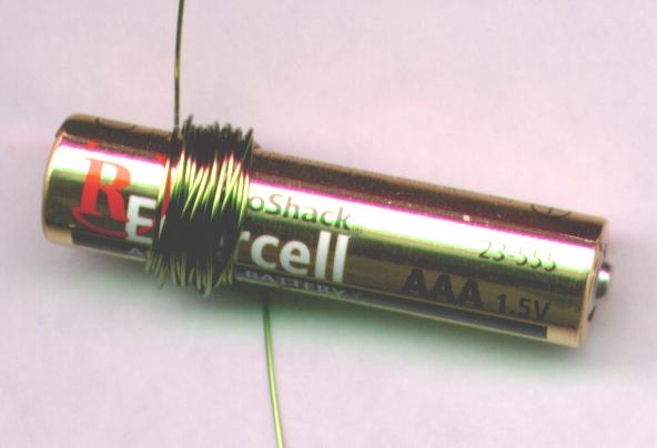
| We start by winding the armature, the part of the motor that moves. To make the armature nice and round, we wind it on a cylindrical coil form, such as a ball point pen or a small AAA battery. The diameter is not critical, but should be related to the wire size. Thin wire requires a small form, thick wire requires a larger form. |
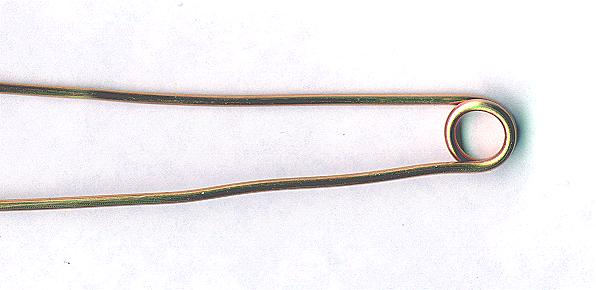
| Leaving a couple of inches of wire free at one end, wind 25 or 30 turns arounf the coil form. Don't try to be neat, a little randomness will help the bundle keep its shape better. The coil will end up looking like the photo below: |
 |
| Now carefully pull the coil off of the form, holding the wire so it doesn't spring out of shape. |
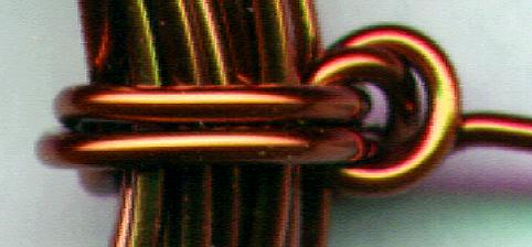
| To make the coil hold its shape permanently, we will wrap each free end of the wire around the coil a couple of times, making sure that the new binding turns are exactly opposite each other, so the coil can turn easily on the axis formed by the two free ends of wire, like a wheel. |
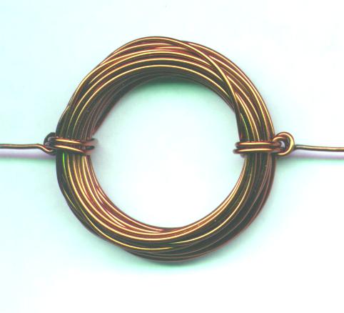 |
| It is not necessary, but I usually wrap a couple turns around these binding turns as well, threading the wire into the space between the large coil and the small coils that hold it together. This makes for a neat, tight package, as in the photo below: |
 |
| If this method of holding the coil together is too difficult, feel free to use scotch tape or electrical tape to do the job. The important thing is to keep the coil together, and to have the two ends of the wire anchored well, and aligned in a straight line, so they form a good axle. |
| Now is where the secret trick comes in, the thing that makes the motor work. It is a secret trick because it is a small and subtle thing, and is very hard to see when the motor is running. Even people who know a lot about motors may be puzzled until they examine it closely and find the secret. |
| Hold the coil at the edge of a table, so the coil is staight up and down (not flat on the table), and one of the free wire ends is lying flat on the table. With a sharp knife, remove the top half of the insulation from the free wire end. Be careful to leave the bottom half of the wire with the enamel insulation intact. The top half of the wire will be shiny bare copper, and the bottom half will be the color of the insulation. A quick sketch may help: |
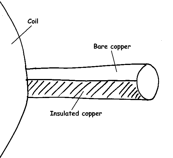 |
| Do the same thing to the other free wire end, making sure that the shiny bare copper side is facing up on both wire ends. |
| The idea behind the trick is that the armature is going to rest on two supports made of bare wire. These supports will be attached to each end of the battery, so electricity can flow from one support into the armature and back through the other support to the battery. But this will only happen when the bare half of the wire is facing down, touching the supports. When the bare copper half is facing up, the insulated half is touching the supports, and no current can flow. |
| The next step is to make the axle supports. These are simple loops of wire that hold up the armature and allow it to spin. They are made of bare wire, since they will also act to get electricity to the armature. |
| Take a stiff piece of bare wire (copper or brass will work, as will a straightened paper clip) and bend it around a small nail to make a loop in the middle, as shown in the photo below. Do the same to another wire, so you have two supports. |
 |
| The base for this first motor will be the battery holder. It makes a nice base because it is heavy when the battery is installed (so the motor won't wobble) and because it has convenient holes in the plastic where we can attach the bare wire armature supports. |
| Attach the support wires securely to the battery holder by winding the free ends several times through the small holes in the plastic at each end. Bend the support wires so the rings are just far enough apart for the armature to spin freely. Bend them apart a little and insert the armature into both rings, then bend them back so they are close to the coil, but not touching it. |
| Insert the battery into the holder. Place the magnet on top of the battery holder just underneath the coil. Make sure the coil can still spin freely, and that it just misses the magnet. |
| The finished motor looks like this: |
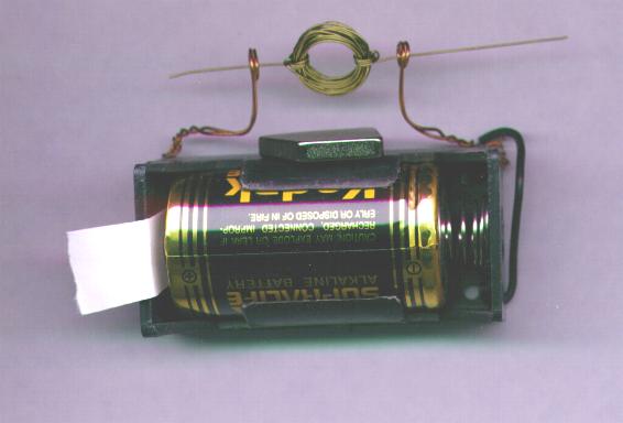 |
| Note that there is a strip of paper stuck in between the battery and the electrical contact in the holder. This is the on/off switch. Remove the paper to allow electricity to flow into the motor, and replace the paper when you want to stop the motor and save the battery. |
| Spin the armature gently to get the motor started. If it doesn't start, try spinning it in the other direction. The motor will only spin in one direction. |
| If the motor still doesn't start, carefully check all the electrical connections. Is the battery connected so one support touches the positive end of the battery, and the other touches the negative end? Is the bare copper half of the armature wire touching the bare support wires at the bottom, and only at the bottom? Is the armature freely spinning? |
| If all these things are correct, your little motor should be spinning around at a pretty fast rate. Try holding it upside down. The motor should spin in the opposite direction if the magnet is on top instead of on the bottom. Try turning the magnet upside down and see which direction the motor spins. If you want a motor that has the magnet on the side instead of the top or bottom, you can simply make a new armature, but this time lay the coil flat on the table when you scrape the insulation off of the top half of the free wire ends. |


0 comments:
Post a Comment